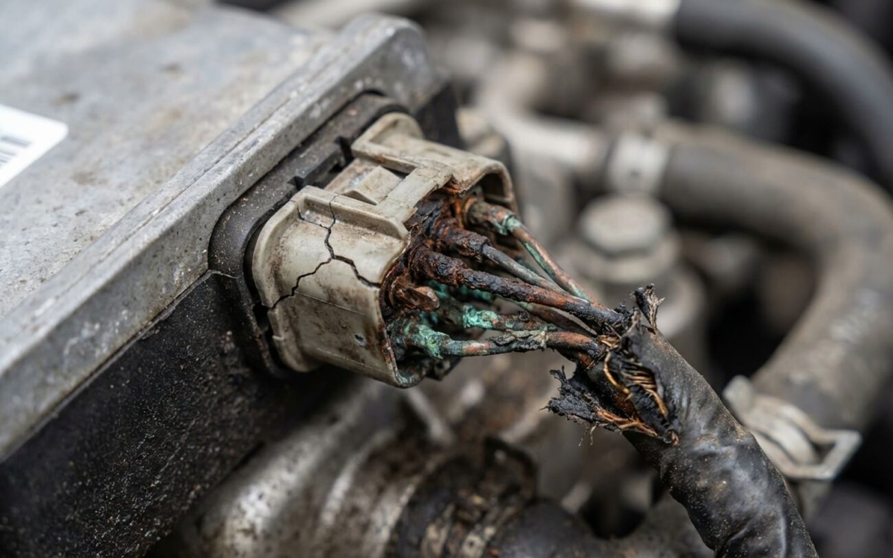
When the Steering Goes Dead: Spotting a Failed EPS Module
When a car comes into my shop with steering that’s suddenly heavy as a truck from the 70s – no power assist at all – my mind immediately goes to the electronic power steering (EPS) system. We’re not talking about a gradual stiffening here. This is an instantaneous, “oh crap” moment, whether you’re backing out of a parking spot or doing 70 on the interstate.
That sudden, complete loss of assist is the biggest telltale sign that the EPS control unit itself has gone belly-up, or it’s lost all power or command signals. You’ll almost always see an EPS or steering warning light glaring at you on the dash, and there will be a diagnostic trouble code (DTC) stored.
EPS SYSTEM MONITOR
Signal: LOST
Now, that warning light could also mean a bad torque sensor or a failing motor, but the key, again, is that sudden and total loss of assist. If I hook up my professional scan tool and can’t even talk to the EPS module – especially after I’ve already verified it’s got good power and ground – then I’m looking at a dead or severely compromised module.
The Concept
“It’s like trying to steer a ship with a broken rudder—the mechanical connection remains, but the power to move it is gone.”
I’ve seen this misdiagnosed more times than I can count. Shops jump straight to replacing the module without checking the basics, only to have the new one fail because of an undetected wiring issue. And let me tell you, driving with no power steering isn’t just a pain; it’s genuinely dangerous.
My Diagnostic Flow: Isolating the True Cause
Before I ever condemn an EPS control module, I make sure to rule out everything else that can mimic its failure. It’s easy to assume a dead module, but often it’s something simpler: a blown fuse, a corroded connector, or a failing sensor. My goal is always to confirm if the fault is inside the module or if something external is causing it to act up. Here’s how I break it down:
| Symptom | Likely in EPS Module | Common External Mimics | My Definitive Test |
|---|---|---|---|
| No assist, EPS light, “Internal Control Module” DTC | Usually an internal short, maybe the microcontroller or power supply circuitry is fried. | Could be a bad torque/angle sensor, or the EPS motor itself is failing and overloading the module. |
Try commanding the EPS motor with your scan tool. If the module still throws an internal fault, even after you’ve confirmed good power and ground, then it’s definitely internal. |
| No assist, no communication, no power | Screams catastrophic internal short, like a failed MOSFET, causing the module to go completely dark. | Check for a blown main EPS fuse (the big 80A one), an open circuit, or damaged CAN bus wiring first. |
Measure battery voltage right at the module’s main power terminal and do a voltage drop test on the ground. If those are good, and still no comms, the module’s likely toast. |
| Intermittent loss of assist | Tricky one. Could be an intermittent internal short or thermal breakdown in the power stage – works until it gets hot. | More often, it’s a loose connector, a dying battery, or a poor grounding point causing voltage fluctuations. |
Monitor current draw with a lab scope. Sudden, erratic spikes usually point to an internal electrical fault within the module. |
The critical takeaway:
Here’s the critical takeaway, and something I preach in my shop: too many technicians blame the module without properly verifying all the external circuits. A short in the torque sensor wiring or a seized EPS motor can overload the module, making it look like the module failed, but they’re not the same thing. Always, always test those sensors, fuses, and wiring first. It saves a lot of headaches and unnecessary parts.
Why They Fail: Root Cause Analysis
Once I’ve definitively isolated the fault to the EPS module itself, it’s time to think about why it failed. Most internal failures happen on the printed circuit board (PCB), not usually in the housing or connectors. The root causes generally fall into a few predictable categories:
-
Failed Solder Joints: I see these a lot, especially on high-current components like the MOSFETs. Thermal cycling and vibration over time just crack those joints. That’s a board-level problem, not a harness issue.
-
Electrical Overstress: If there’s an internal short in the EPS motor, it can send a massive current surge right back into the control module, frying the driver transistors. They’re just gone, permanently.
-
Contamination: Coolant leaks, battery acid, or even road salt can seep into the module housing. Once it’s in there, it’ll corrode PCB traces or create a direct short circuit.
-
Microcontroller Failure: The module’s “brain” can just give up the ghost, often due to voltage regulator issues or simply old age. High-temperature operation often leads to those tiny solder joints on the power supply board cracking.
The Fix: My Recommended Resolution Pathways
Professional Territory Only
Alright, so you’ve confirmed it’s the module. What now? This isn’t a DIY job for modern vehicles, let me be clear. You’re dealing with integrated immobilizers and CAN bus security, so you need OEM-level diagnostic tools and programming capabilities.
External Connector Repair
PCB-Level Repair
Full Module Replacement Standard Fix
Post-Repair Validation: Don’t Skip This Step
Replacing the module isn’t the end of the job; you’ve got to validate the repair. I always start with a static test: engine running, turn the wheel slowly lock-to-lock. The assist should feel smooth and consistent. Listen for any weird motor noises – grinding or groaning can mean a mechanical issue or that the calibration isn’t quite right.
My Validation Checklist
-
Verify there are no active or pending DTCs in the EPS system or any related modules. Don’t just clear them and call it a day.
-
Check that the steering angle sensor reads zero (within ±2°) when the wheels are perfectly straight. This is critical for stability control.
-
Monitor live data: the torque sensor values should change smoothly and predictably as you turn the wheel.
-
Finally, a good road test. Drive it at various speeds and conditions to confirm the assist works everywhere it should.
Cost, Risk & The Economic Decision
Now, let’s talk brass tacks – what’s this going to cost you, and is it worth it? These are always tough conversations with customers.
Used Module Swap
High risk, honestly. You’re often dealing with programming or immobilizer incompatibility. In my experience, the success rate is less than 50%.
Full Replacement
This is the standard shop cost, covering parts, labor, and that essential OEM programming. You’re looking at about a 95% success rate with this approach.
Specialist PCB Repair
Lower upfront cost, but it carries the risk of latent damage that can lead to re-failure down the road. It’s a gamble.
Prevention & Monitoring
A few tips to keep your EPS happy, or at least catch problems early: Always make sure your alternator output is within spec – I like to see it between 13.8–14.8V. Chronic undercharging really stresses those internal regulators in the module. And do a quick search for any recalls on your specific vehicle model. Manufacturers sometimes have known weaknesses that can affect the steering system, like premature tie rod end wear.
