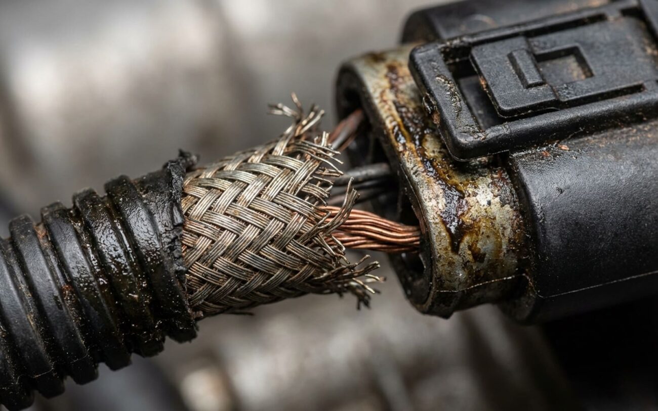
Alright, let’s talk about one of the most frustrating problems that rolls into my bay: intermittent electrical glitches caused by a failing shielded wire. After 25 years of turning wrenches, I can tell you these aren’t your typical open or short circuits. No, these are the kind of gremlins that make you pull your hair out, because they come and go, often without rhyme or reason—or so it seems at first.
What You’re Dealing With: EMI and a Compromised Shield
The core issue here is electromagnetic interference (EMI). Think of it like trying to have a conversation next to a loud construction site. The message (your sensor signal) is there, but all the surrounding noise makes it impossible to understand. That’s what happens when EMI gets into a low-voltage signal wire. The computer (PCM) gets “implausible signals,” which means it’s hearing gibberish.
Every critical sensor wire—crankshaft position, camshaft position, MAF, sometimes even O2 sensors—has a shield. It’s usually a braided copper sleeve wrapped around the signal wire, and it’s designed to act like a miniature Faraday cage. Its job is to catch all that electrical noise from ignition systems, alternators, power windows, you name it, and safely shunt it to ground before it can mess with the signal. When that shield gets damaged or loses its ground connection, it stops doing its job. And that’s when the trouble starts.
The Classic Symptoms I See
The dead giveaway for EMI is an unpredictable sensor reading that only acts up when another electrical system activates. I’ve seen MAF sensor values spike like crazy every time someone rolls down a power window. Or a crankshaft position sensor signal drop out for a split second when the fuel pump kicks on. If you’re watching live data and see a sensor signal suddenly jump or flatline, then return to normal, especially when something else cycles on, that’s a huge red flag.
You’ll often pull codes like P0335 (crankshaft position sensor circuit malfunction), P0340 (cam sensor), or even P0102/P0103 (MAF sensor) – but pay close attention to the descriptors. If it says “intermittent” or “implausible signal,” your EMI antenna alarm should be blaring.
Sometimes, you might even spot the damage visually: a break in the outer insulation, exposing the shiny metal braid underneath. That’s a solid clue, but often, the damage is hidden inside the harness or at a poor ground connection.
EMI SIGNAL MONITOR
Noise Floor: 450mV
My Approach to Diagnosis: Isolating the Real Problem
The biggest challenge with EMI is that its symptoms mimic a bunch of other common problems: a failing sensor, corroded connector, or even a weak system ground. Jumping straight to a wiring repair without ruling these out is a surefire way to waste hours and throw parts at a problem. You’ve got to isolate whether the issue is truly in the shield or somewhere else.
Where I Start: Visuals and Basic Checks
-
Inspect the harness: Look for any obvious signs of damage—chafing, cuts, melted insulation, or exposed braid. Pay close attention to areas where the harness bends sharply or rubs against engine components or the firewall.
-
Check connectors: Disconnect and inspect sensor connectors for corrosion, bent pins, or poor terminal tension. This is a common culprit for intermittent signals, regardless of EMI.
-
Verify system grounds: A bad engine or chassis ground can cause all sorts of weird electrical issues. Check main battery grounds, engine-to-chassis grounds, and especially the PCM ground points. I’ve seen more than one intermittent crank sensor code fixed by simply cleaning and retorquing a loose PCM ground screw.
The Definitive Test: Oscilloscope is Your Best Friend
If the basic checks don’t reveal anything, you need an oscilloscope. This is where you separate the part-swappers from the diagnosticians. Here’s what I do:
- Connect the scope: Hook up your oscilloscope to the signal wire of the suspect sensor.
- Static check: With the engine off, just observe the signal. It should be flat or show a clean reference voltage.
- Dynamic check (engine running): Start the engine and let it idle. Observe the sensor’s waveform. It should be clean and consistent.
- Introduce noise: This is the critical step. While watching the scope, start cycling known noise sources. Turn on the A/C, roll up/down the power windows, activate the fuel pump (if you can manually), cycle the cooling fan, or even just rev the engine. If you see high-frequency “hash,” erratic spikes, or momentary dropouts on your sensor signal when these other systems activate, you’ve found your EMI.
This dynamic test is key. It tells you if the shield is failing to protect the signal from external electrical noise. You’re looking for that noise floor to jump significantly (like the “450mV Noise Floor” you see in the diagnostic graphic) or for the signal to become visibly distorted.
Testing the Shield Itself
Once you suspect the shield, you need to verify its integrity. The shield’s job is to ground that noise, so its connection to ground is paramount.
-
Shield Ground Resistance: Locate where the shield’s drain wire (it’s usually a single wire coming off the braid) connects to ground. This could be at the sensor connector, within the harness, or at the PCM. Measure the resistance from this drain wire to a known good engine ground. I’m looking for less than 0.5 ohms. Anything higher, and that shield isn’t doing its job effectively.
-
Continuity (if visible damage): If you see exposed braid, carefully check for continuity between that exposed metal and the designated ground point. If it’s open, the shield is physically broken.
Why Shields Fail: Common Root Causes
From my experience, shield failures usually boil down to a few things:
-
Material Degradation: Copper braid doesn’t last forever. It can corrode when exposed to coolant, road salt, battery acid, or even just moisture over time. You’ll see it turn green and get brittle. Corrosion means increased resistance, and that turns your effective shield into a poor conductor, or worse, an open circuit.
-
Mechanical Fatigue: Vibration is a killer in an engine bay. The fine wires of the braid can fracture at tight bends, or where the harness rubs against a bracket or firewall. This is especially common near connectors where the wire is often flexed.
-
Poor Termination: Honestly, this is the weakest point in most designs. The shield’s drain wire needs a solid, low-resistance connection to ground. If that connection is loose, corroded, or was poorly made at the factory, the whole shield is useless. I’ve seen several service bulletins for certain model years where the shield drain wire was either omitted or misrouted during assembly, leaving sensors wide open to ignition system noise.
Fixing It Right: Repair Pathways
This Isn’t a Simple Wire Splice
You’re repairing a shielded circuit, often a twisted pair. If you mess this up, you’ve created an antenna instead of a shield, and you’ll make the problem worse. If you’re not comfortable with terminal extraction, soldering, and using adhesive-lined heat shrink, you need to seek professional help. Seriously, don’t hack this job.
Post-Repair Validation: Prove It’s Fixed
Clearing codes isn’t enough. You absolutely must prove the repair worked. For shield repairs or ground fixes, my validation process has two parts:
- Static Check: First, measure the resistance from your repaired shield ground connection to a known good engine ground. It must be less than 0.5 ohms. If it’s not, you haven’t fixed the ground.
- Dynamic Test (The Real Proof): This is the critical step. Get your oscilloscope back out. With the engine running and all accessories on, monitor the sensor signal you just repaired (e.g., crankshaft position sensor). Now, cycle those high-load devices again—the starter, power windows, A/C compressor, cooling fans. A truly clean signal should show a smooth, consistent waveform with no high-frequency “hash” or erratic voltage spikes. If you still see noise, the shield is still compromised, or you’ve got another noise source you haven’t identified.
Prevention: Keeping the Noise Out
My Maintenance Checklist
-
Route Wires Correctly: Always keep shielded wires away from high-current cables like alternator output leads, starter leads, or ignition coil wiring. The further apart, the better.
-
Secure Harnesses: Make sure all harnesses are secured in their factory clips. This prevents vibration and chafing against brackets, which is a major cause of mechanical fatigue.
-
Quick Ground Check: During any electrical troubleshooting, especially for intermittent issues, it’s a good habit to perform a quick resistance test from any accessible shield drain wire to the engine block. It takes seconds and can save hours.
