Moisture in a hybrid inverter? Yeah, I’ve seen it more times than I can count over the last 25 years. It’s one of those problems that can sneak up on you, but when it hits, it can be a real killer for your hybrid system. This isn’t just about a little dampness; we’re talking about high-voltage electronics getting compromised, and that’s serious business. Let me walk you through what I’ve learned about diagnosing and dealing with it.
The First Clues: What You’ll See and Hear
When moisture breaches an inverter, the symptoms can be subtle at first, or they can hit you like a ton of bricks. But here’s the kicker: they’re almost always tied to the weather. One minute the car’s running fine, the next you get a “Check Hybrid System” or “Power Reduced” warning. And usually, it happens right after you’ve driven through a big puddle, in heavy rain, or even just on a really humid morning. That weather connection? It’s your first big clue, and it’s almost never wrong. Unlike an inverter that’s just overheating, which is usually predictable, moisture faults are erratic and directly linked to environmental dampness.
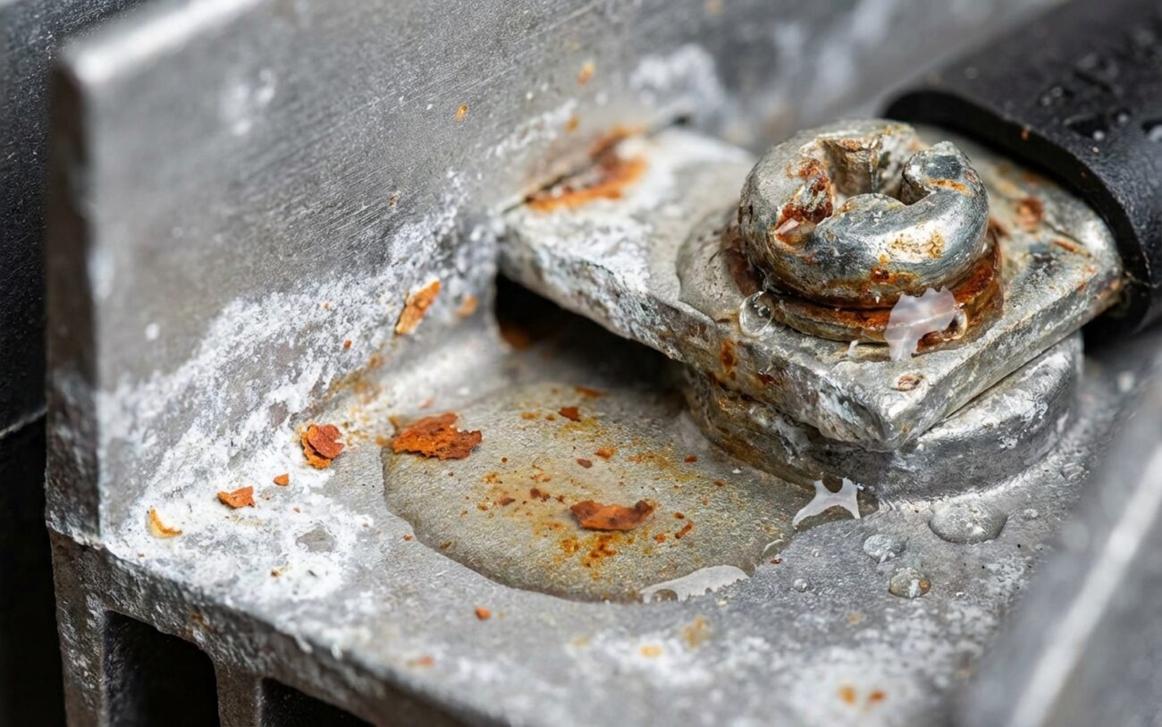
Physically, I always tell customers and junior techs to look for white or greenish crust around the inverter’s cooling fins or high-voltage connectors. That’s classic electrolytic corrosion, a dead giveaway. In more advanced cases, you might even see dark carbon tracking or flash marks on the plastic housing. That means electricity has been arcing across wet or contaminated surfaces, and that’s really bad news.
Inside the inverter’s control module, you’ll find fault codes specifically for insulation breakdown. The most common one I see is an isolation fault, like P0AA6 (Hybrid/EV Battery System Isolation Fault) or a manufacturer-specific version like P0A1D. What these codes mean is simple: the system detected high-voltage current leaking to ground. And guess what moisture does? It creates a conductive path, bridging where it shouldn’t. If the fault is severe enough, the inverter will shut down the entire high-voltage system instantly to protect itself from catastrophic damage. Once that internal short path forms, failure can be both rapid and irreversible.
Is It Really the Inverter? How I Rule Out Other Stuff
Now, it’s easy to point fingers at the inverter when those isolation codes pop up, but you’ve got to be careful. Other high-voltage components can throw the exact same symptoms and codes. I’ve seen damaged hybrid battery packs, compromised motor windings, or even a chafed high-voltage cable trigger identical warning lights. And that external corrosion on the inverter housing? Sometimes that’s just road salt or a coolant leak from something nearby; it doesn’t automatically mean the inverter itself is toast internally. To truly confirm the source, you have to isolate and test the inverter independently. Visual clues help, but they’re not the final word.
Here’s how I approach it:
- For an Isolation Fault Code (like P0AA6): This is where a good dielectric withstand (Hi-Pot) test comes in. You absolutely must disconnect all high-voltage cables from the inverter. Then, apply 1000V DC between the DC terminals and the inverter casing. If you read anything below 10 MΩ, you’ve got an insulation breakdown, and that inverter is likely compromised internally. This test isolates the inverter from the rest of the HV system, so you know exactly where the fault lies.
- For Visible Corrosion on the Housing: Clean the housing thoroughly first. Then, if possible, use a borescope to inspect inside through any available ports or breather valves. If you see moisture trails or corrosion on internal busbars, that confirms the external breach led to internal damage. If it’s clean inside, the external corrosion is likely just cosmetic or from an external source.
How That Moisture Actually Kills Your Inverter
The inside of an inverter is designed to be bone dry and precisely temperature-controlled. When moisture gets in—and it usually does through a failed seal, a degraded O-ring, or a compromised breather valve—it kicks off a nasty chain reaction. Think about it: the inverter heats up during operation, often well over 150°F, then cools down overnight. This constant thermal cycling turns any trapped moisture into condensation, right on the circuit boards and high-voltage components.
That condensation isn’t just plain water; it becomes an electrolyte. This enables something called electrochemical migration. Over time, tiny conductive metal filaments, known as dendrites, start to grow across the PCB traces. Eventually, they create low-resistance short circuits. It also accelerates galvanic corrosion where dissimilar metals meet, like copper busbars bolted to aluminum cooling plates. I’ve seen this eat through terminal connections completely in less than two years, especially in humid or coastal climates.
Another hidden issue is micro-cracking in the epoxy potting compound that encapsulates sensitive circuitry. That constant thermal expansion and contraction can create hairline fractures, letting moisture seep into areas that should be perfectly sealed. While I can’t cite specific TSB numbers, I know several manufacturers, including Toyota on some of their hybrid models, have issued service advisories for inverter breather valve designs that just don’t hold up under high humidity, leading to those recurring P0A1D-type codes.
Now, a critical point: not every overheating inverter has an internal moisture fault. A clogged cooling line, a failed coolant pump, or even an air pocket in the coolant loop can cause thermal shutdowns that look like moisture damage but are actually external cooling system problems. Always verify the root cause before you condemn the whole unit; I’ve seen good inverters replaced because someone missed a simple cooling issue.
Professional Territory Only
Let me be crystal clear: this ain’t a DIY job. You’re talking about lethal voltage here—often over 300V DC. You need specialized training, tools, and strict safety protocols to even think about touching these components. Seriously, don’t mess around with this unless you’re certified.
Your Repair Options, From Simple to Severe
External Seal or Connector Issues PROFESSIONAL-ONLY due to HV safety risks
Minor Internal Corrosion – PCB Cleaning and Re-Coating PROFESSIONAL-ONLY – SPECIALIZED REPAIR
Severe Internal Damage – Replace the Assembly NON-REPAIRABLE → REPLACE ASSEMBLY
Temporary Measure – Controlled Drying (Use with Caution) TEMPORARY / LAST-RESORT
Proving the Fix Actually Worked
Never, ever assume a repair is complete just because the warning light is gone. Validation is absolutely essential to avoid comebacks and keep your reputation intact.
- For an External Seal Repair: After reinstallation, perform another Dielectric Withstand Test. Some shops, including mine, will also simulate real-world exposure by gently spraying the repaired area with water (with the system powered down, of course) and then using a borescope to check for any new ingress. If that seal is good, you won’t find any new moisture inside.
- For a Cleaned and Recoated PCB: This is the tricky one. The inverter should undergo a thermal cycling bench test for at least 24 hours. You need to monitor the insulation resistance with a megohmmeter at both ambient (around 70°F/20°C) and elevated temperatures (around 120°F/50°C). A stable reading above 10 MΩ throughout that entire cycle indicates a successful repair. Any fluctuations or drops suggest residual contamination or hidden damage you missed.
- After a Full Assembly Replacement: Conduct a complete hybrid system check. Run the vehicle through its full drive cycle to clear all monitors, then scan for fault codes. You should see zero isolation faults. Additionally, use a clamp-type milliammeter on the HV ground cable to measure leakage current. OEM specs typically require less than 5 mA; anything higher suggests a lingering insulation issue somewhere in the system.
The Cold, Hard Economics of Fixing It
Repair costs for inverter moisture damage vary widely, and this is where the decision often comes down to the vehicle’s value and how long you plan to keep it. The table below gives you a realistic idea of average shop costs and the likely outcomes.
| Repair Type | DIY Cost | Shop Cost | Success Rate | Secondary Risk if Failed |
|---|---|---|---|---|
| External Seal Replacement | N/A (HV Hazard) | $400 – $800 | High (>95%) | Continued moisture ingress leading to internal PCB or IGBT failure |
| Internal PCB Clean/Recoat | N/A (HV Hazard) | $800 – $1,500 | ~70% | Risk of short circuit under load, potentially damaging HV battery contactors or motor inverter |
| Full Assembly Replacement | N/A (HV Hazard) | $2,500 – $5,000+ | High (>98%) | Financial risk—high cost relative to vehicle value |
Here’s how I approach the cost-benefit conversation with my customers: if a certified remanufactured inverter and its installation cost more than 50% of the vehicle’s current market value as a running hybrid, the repair is hard to justify. That doesn’t mean it’s never worth doing—especially if the car is otherwise in fantastic shape and you love it—but it’s a decision that needs honest financial consideration. I’ve seen owners spend $4,000 to save a $6,000 car, only to face another major repair months later. You really need to know your break-even point.
How to Keep It From Happening Again
Prevention is always your best defense. Most inverters are built to tough standards like IP67, but seals degrade over time, that’s just a fact of life. Keep the cooling fins and ventilation paths clear of leaves, mud, and road debris. Trapped organic material retains moisture and creates a humid microclimate right around the unit, which is exactly what you don’t want.
During routine maintenance, like an oil change or tire rotation, take 30 seconds to visually inspect the inverter housing and its connectors. Look for cracked seals, swollen rubber boots, or any early signs of that white or green corrosion. Catching these things early can save you thousands.
If the inverter ever needs to be opened—say, for a seal replacement—use only OEM-recommended sealants and gaskets. Don’t cheap out with off-the-shelf RTV or generic dielectric grease; they just won’t hold up under the thermal cycling or prolonged exposure these units face. And always apply a high-quality dielectric grease to HV connectors during reassembly. It helps prevent future corrosion and ensures proper electrical contact.
