Alright, let’s talk about one of the most frustrating problems we see in the shop: when your vehicle’s Engine Control Unit (ECU) and the battery monitoring system just stop talking to each other. It’s not always a dead battery or a bad alternator, though those are often the first things folks jump to. More often than not, what we’re really looking at is a breakdown in the Controller Area Network (CAN bus) — the digital nervous system of your car. This network is how modules like the ECU, the battery sensor, and even the body control module (BCM) share critical real-time data. When that communication breaks down, it throws everything into chaos. The ECU loses its eyes on the battery’s voltage, its state of charge, and what the car is demanding in terms of power. That’s a recipe for trouble.
Symptoms: When the Car Starts Acting Confused
The first clue, almost without fail, is going to be in the diagnostic trouble codes (DTCs). I always grab my scan tool first thing. You’ll usually see U-codes — specifically U0100 (Lost Communication with ECM/PCM) is a big one. You might also get manufacturer-specific codes pointing to lost communication with the Intelligent Battery Sensor (IBS) or Battery Management System (BMS). These aren’t telling you a component has failed; they’re shouting that there’s a problem on the network itself. But here’s the catch: these same codes can pop up whether it’s a broken wire, a bad sensor, or even the ECU’s internal network driver acting up. So, don’t jump to conclusions just yet.
On the dashboard, things can get weird. The battery warning light might not behave like it should — maybe it stays on, flickers, or gives you inconsistent voltage readings. On newer, more advanced vehicles, I’ve seen the whole instrument cluster go dark or display a whole Christmas tree of module failures. If you let it go, the car might throw itself into a limp-home mode, shut down non-essential systems, or just refuse to restart after you turn it off. This isn’t just an inconvenience; it’s a sign the network is failing, and that can cascade into bigger electrical headaches. Your ECU needs that battery feedback to manage charging and shed loads when voltage drops. Without it, the system is flying blind, and you’re risking a complete electrical shutdown.
Diagnosis: Is It the Wire or the Box?
Before you start tearing into wiring harnesses or swapping out expensive modules, you’ve got to figure out if the fault is in the CAN bus circuit itself, or if it’s one of the components connected to it. A faulty IBS, a bad ECU, or even a gateway module can perfectly mimic a wiring fault. My approach is to systematically rule things out.
Technician’s Insight:
Let’s be clear upfront: a failed IBS unit or an ECU software glitch is not a CAN bus wiring fault. We’re talking about the actual copper wires, the insulation, and the connector pins. If your tests consistently point to wiring, focus on that physical path between the ECU and battery sensor. Don’t get sidetracked by module theories once you’ve proven the wiring is the problem.
Step 1: Initial Scan and Network Check
First, I always perform a full system scan. Those U-codes are your starting point. If you see U0100 or similar battery module communication codes, I then move to checking the network’s health. With the battery disconnected, I’ll measure the termination resistance at the OBD2 port. A healthy CAN network should read right around 60 ohms. If it’s 120 ohms, you’ve got an open circuit somewhere. If it’s 0 ohms, you’ve got a short. Anything else, and you’ve got resistance issues.
Step 2: Lab Scope for Signal Integrity
This is where a good lab scope really shines. I’ll back-probe the CAN_H and CAN_L wires, ideally as close to the battery sensor or ECU as possible. What you’re looking for is a clean, differential waveform. Both lines should mirror each other, but inverted, with sharp transitions. If you see a flat line, excessive noise, or a distorted signal, you know you’ve got a problem on that specific segment of the bus. This helps differentiate between a module that’s not transmitting and a wire that’s not carrying the signal.
Step 3: Voltage Drop and Short Checks
If the scope shows a signal but it’s weak or intermittent, I’ll perform a voltage drop test on both CAN_H and CAN_L wires while the network is active. Anything exceeding 0.5V indicates high resistance in the circuit, which can degrade the signal. If you’re seeing cascading module faults, where other modules on the same bus are also losing communication, that often points to a short. I’ll then check for shorts: CAN_H to ground, CAN_L to ground, CAN_H to 12V, and CAN_H to CAN_L. A short on either CAN line can pull down the entire network segment.
Step 4: Isolating the Component (If Suspected)
If all the wiring checks seem okay, or if you suspect a module, try disconnecting the intelligent battery sensor (IBS) or battery management system (BMS) module. Clear the codes, then re-scan. If communication returns to other modules on the network, you’ve isolated the fault to either the sensor itself or the short section of wiring directly connecting it. This helps confirm whether the module is dragging down the bus.
Root Causes: Why CAN Bus Wiring Fails
Once you’ve definitively confirmed the issue is in the wiring — and not the modules — you’re dealing with physical degradation of that CAN bus circuit. Those two twisted wires (CAN_H and CAN_L) are designed to be tough and resist noise, but they’re not invincible. In my experience, the most common failures come down to environmental exposure and good old mechanical stress.
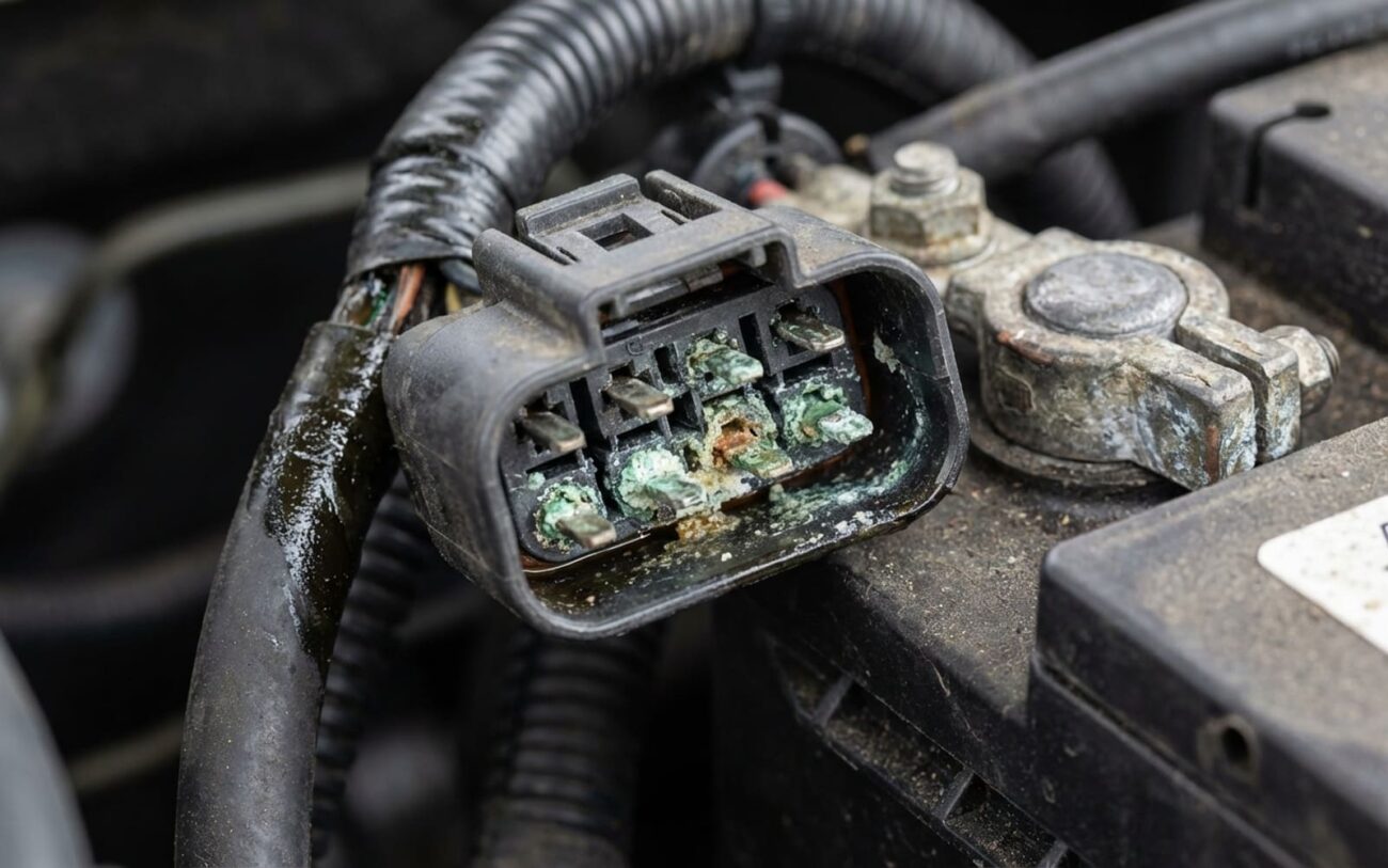
Corrosion is a huge culprit, especially in areas like the engine bay or near the firewall where moisture can get into connectors. I’ve pulled apart battery sensor connectors after just a few years in humid climates and found pins completely covered in green oxidation. That corrosion builds up resistance and completely disrupts the signal. It’s not the sensor that’s bad; it’s the connection. Vibration is another silent killer. In engine bays, constant movement can fatigue the fine strands inside the wires, especially where they’re routed tightly or near grommets. Over time, this leads to intermittent opens or high-resistance joints that are a nightmare to track down.
Then there’s physical damage. The harness can rub against sharp edges — battery hold-down clamps, sheet metal seams — wearing right through the insulation. When CAN_H or CAN_L shorts to ground, or even to each other, it can drag down the entire network. I’ve seen this happen repeatedly on vehicles where the harness wasn’t properly secured after a battery replacement. And let’s not forget poor aftermarket repairs: those quick-fix “vampire taps” or cheap crimp connectors slapped onto CAN wires introduce impedance mismatches and are notorious for failing, causing all sorts of intermittent communication issues.
Some vehicle platforms even have known issues. For example, I’ve seen certain FCA models where the CAN harness near the battery tray is prone to abrasion due to factory routing. Always check for manufacturer service bulletins covering harness routing or protection if you’re working on a known problem area.
Resolution: Fixing It Right
How you fix it really depends on where the fault is and how bad it is. Having the right tools and good accessibility makes all the difference.
Accessible Wire Repair DIY-FEASIBLE
Sealed Connector/Pin Repair Professional Only
Module Replacement & Coding
Temporary Bypass (Diagnostic Only)
Post-Repair Validation: Making Sure It Stays Fixed
A repair isn’t truly complete until it’s validated. First, clear all DTCs with a capable bidirectional scan tool. Then, I always perform a full drive cycle: start the engine, let it warm up, and drive it through a range of speeds and loads. Afterward, re-scan the system. The goal is zero U-codes or intermittent network faults returning.
For a wiring repair, the gold standard in my shop is an oscilloscope check right at the battery sensor connector. Back-probe the CAN_H and CAN_L pins. You should see a clean, stable differential signal with sharp transitions and absolutely no excessive noise or ringing. Any distortion here suggests an impedance mismatch or a poor splice that will cause problems down the road.
If you replaced a module, validation means confirming live data flow. Use your scan tool to monitor battery voltage, state of charge, and current draw from the new module. The ECU should now recognize the sensor and respond intelligently to load changes. If it doesn’t, chances are the programming step either failed or wasn’t completed fully. The same tools you used for diagnosis — your scan tool, multimeter, and scope — are the ones you need for this final verification.
Cost, Risk & The “Is It Worth It?” Question
Repair costs can vary wildly depending on the root cause and how much labor is involved. Here’s a general idea of what I see:
| Repair Type | DIY Cost | Shop Cost | Success Rate | Secondary Risk if Failed |
|---|---|---|---|---|
| Simple Wire Splice | $20 | $150–$300 | >95% | Intermittent faults may return; a poor repair can introduce noise, destabilizing the network. |
| Connector/Pin Repair | $50–$100 | $300–$500 | >90% | Damaged connector housing may require full harness replacement—a much more expensive repair. |
| ECU or IBS Replacement | $800–$1800 | $1000–$2500 | 100% (if programmed correctly) | Incorrect programming can permanently disable (“brick”) the module, making it unusable. |
This brings us to a critical decision point for many customers. If you’re looking at a faulty ECU and the repair cost starts to creep past 50% of the vehicle’s current value, you really have to consider whether replacement is the most economical choice. Sure, used modules are an option, but they almost always need coding, and their reliability is always a bit of a gamble. At that point, it’s not just a technical fix anymore — it’s a serious financial calculation.
Keeping It Healthy: Prevention & Monitoring
Proactive Maintenance Tips from My Bench
-
Whenever I have the battery out, I always take a minute to inspect the harness routing near the tray. Make sure it’s not pinched, stretched, or rubbing against any metal edges. A few seconds here can save hours later.
-
A little dielectric grease on the battery sensor connector seal goes a long way to prevent moisture from wicking in. It’s a small, cheap step that really pays off in long-term reliability.
-
Incorporate network health into your regular scan tool checks. Even if the check engine light isn’t on, look for stored or pending U-codes. Catching an intermittent fault early can prevent a full breakdown.
