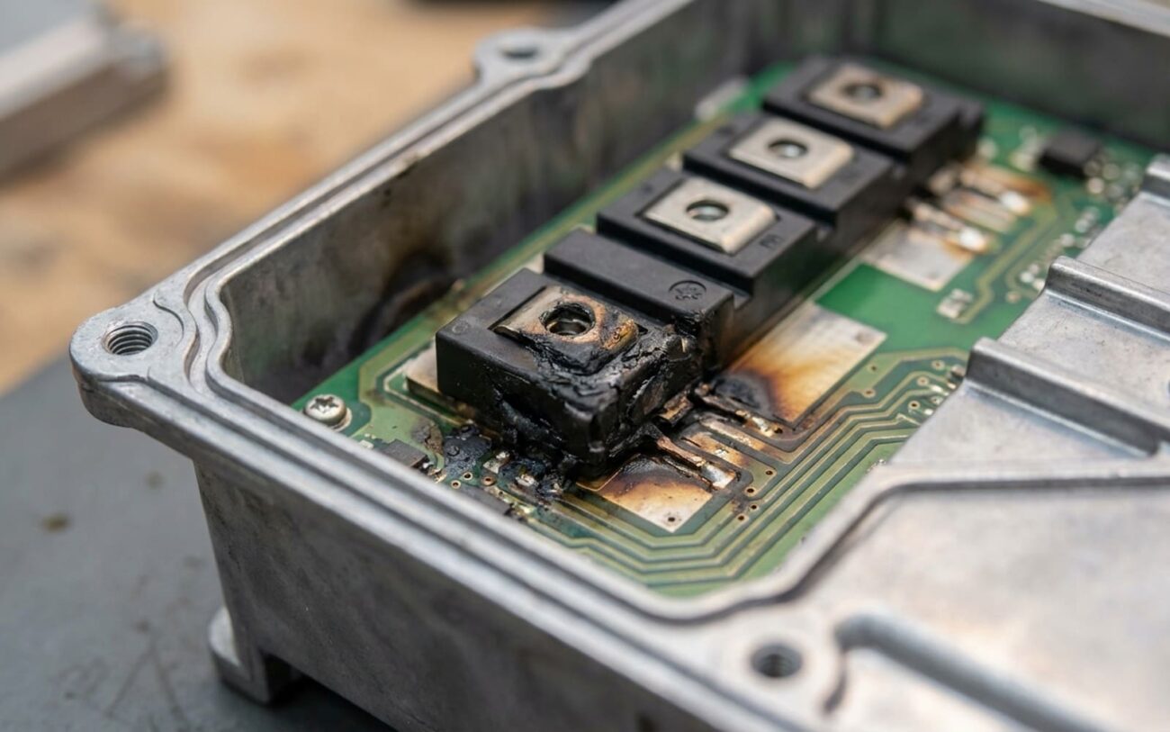
Alright, let’s talk about one of the most frustrating failures in an EV or hybrid: that sudden, dead stop. You’re driving along, battery gauge looks fine, and then… nothing. No power to the wheels. In my 25+ years turning wrenches, when I see this, my first suspect is almost always the inverter. It’s the brain and brawn that translates the battery’s DC power into the AC juice your electric motor needs to spin the wheels. And inside that inverter, the real heavy lifting is done by components called IGBTs – Insulated-Gate Bipolar Transistors. Think of them as super-fast, high-power electronic switches, pulsing on and off thousands of times a second to perfectly control the motor.
What You’ll See (and Hear) When an Inverter Goes Bad
When an IGBT inside that inverter decides to quit, it usually does so dramatically. Most often, it’s a catastrophic internal short. The car’s computer senses this overload instantly and, for your safety and to prevent a bigger meltdown, it cuts power. That’s why you’re suddenly stranded. Sometimes, right before it dies, you might hear a distinct buzzing, a crackle, or even a loud pop from under the hood – that’s electricity arcing where it shouldn’t be, usually through damaged components or insulation.
But often, the car gives you a heads-up before the full shutdown. The control modules are always watching, and they’ll throw a Diagnostic Trouble Code (DTC). Things like P0A1F (Drive Motor “A” Performance) or P0A3A (Inverter Performance) are big red flags. These codes usually point to internal inverter problems: a phase imbalance, an IGBT that’s not turning off correctly (what we call ‘desaturation’), or a problem with the gate driver that controls the IGBT. If an IGBT really shorts out hard, it can even blow the pyro-fuse – that’s a one-time-use, high-voltage fuse designed to disconnect the battery in a major fault. If that’s blown, nothing’s moving until it’s replaced, and you’ve got to find out why it blew in the first place.
Why These Things Fail: The Real Root Causes
It’s not like an IGBT just “burns out” for no reason, like a light bulb. These failures are almost always due to cumulative stress, primarily thermal and electrical. You’ve got a solid-state device, but it’s living in a brutal environment: huge currents, lightning-fast switching, and constant temperature swings.
The biggest killer I see is thermal cycling fatigue. Think about it: every time you stomp on the accelerator, especially with regenerative braking, that IGBT heats up fast and then cools down just as quickly. Over thousands of cycles, that constant expansion and contraction stresses the tiny aluminum bond wires that connect the silicon chip to the rest of the package. Eventually, they crack or lift off – just like bending a paperclip back and forth until it breaks. Once that connection is gone, the IGBT can’t do its job, it overheats, and then it usually shorts out.
I also see a lot of solder fatigue where the silicon die is bonded to the baseplate. If the thermal expansion rates aren’t perfectly matched, you get microscopic cracks in the solder. That means poor heat transfer, localized hot spots, and accelerated failure. I’ve opened up modules where the silicon itself was charred black, all from a tiny crack that started months earlier.
Less common, but just as destructive, are electrical failures. A big voltage spike, maybe from the motor’s inductance during a hard regen event, can exceed the IGBT’s gate voltage rating. That damages the delicate oxide layer that controls the switch. Once that’s compromised, the gate loses control, and the IGBT can stick “on,” causing a dead short. There’s also something called latch-up, where a parasitic circuit inside the IGBT gets triggered and can’t be turned off, leading to uncontrolled current flow. Either way, it’s bad news.
Now, it’s important to remember that not every inverter problem is an IGBT problem. A leaky coolant passage, a bad capacitor, or a cracked circuit board trace can mimic these symptoms. For instance, on some older Toyota Prius models and early Teslas, bond wire fatigue in the IGBTs was a known issue under heavy use, often throwing a P0A3A. But those are specific component weaknesses, not a sign that the whole inverter design is flawed.
My Diagnostic Flow: Separating Inverter Failure from Look-Alikes
Here’s the thing about inverter symptoms: they’re tricky. They often look exactly like other high-voltage system failures. A car that won’t move? Could be a failed contactor in the battery pack, a ground fault, or even something mechanical in the transaxle. That buzzing sound? Might be a dying DC-link capacitor or a noisy motor resolver, not necessarily the IGBTs. Even those specific fault codes like P0A1F or P0A3A can pop up due to wiring problems, bad sensors, or even just a weak 12-volt supply to the inverter’s control board. Trust me, I’ve chased my tail on these more than once.
That’s why you can’t just assume the inverter is dead. You need a structured approach. Jumping to conclusions just wastes time and money. This is the real-world diagnostic chart I use in my shop to pinpoint whether it’s truly an IGBT issue or something else entirely.
| What You See / Code | Points to IGBT/Inverter | Common Mimics (Don’t Get Fooled) | The Definitive Test I Use |
|---|---|---|---|
| P0A1F: Drive Motor “A” Performance | Phase loss from a shorted or open IGBT | Faulty motor resolver, damaged motor winding, mechanical binding in the transaxle |
Static IGBT Test: First, disable all high-voltage. Disconnect the three-phase motor cables. Then, use a good DMM to measure resistance between each phase terminal (U, V, W) and both the DC+ and DC– terminals of the inverter. If you see anything below 1 MΩ, you’ve got a shorted IGBT. |
| P0A3A: Inverter Performance | Desaturation fault or gate driver failure in an IGBT module | Low 12V supply to the inverter control board, corroded signal connector, faulty control board itself |
Gate Signal Analysis: With HV disabled, use an oscilloscope. Monitor the gate-emitter voltage signals directly on the gate driver board. Command inverter operation (via a factory scan tool if possible). Look for missing or distorted gate signals – that tells you if the driver is failing. |
| “Car Won’t Move” with HV Battery Active (but no motor) | Pyro-fuse blown due to an IGBT short to ground or internally | Failed main contactor in the battery, battery management system (BMS) isolation fault, or even a bad 12V battery |
Pyro-fuse & Insulation Test: First, check continuity of the pyro-fuse with a multimeter – it’s usually a visual inspection or a simple resistance check. If it’s blown, you know why you have no power. Then, and this is critical, perform an insulation resistance test between the inverter’s DC input terminals and the chassis ground using a megohmmeter. You’re looking for any leakage that indicates a short to ground. |
| Overheating DTCs (e.g., P0A80: Inverter Coolant Temp Sensor) | Failed IGBT causing excessive heat in one phase leg, or general inverter overheating | Low or degraded inverter coolant, failed dedicated inverter coolant pump, clogged radiator or heat exchanger for the inverter circuit |
Coolant & Thermal Scan: First, verify the inverter’s coolant level and flow through the system. If that’s good, use a thermal imaging camera (FLIR gun) on the inverter housing during a controlled power-up or light load. Look for specific hot spots or uneven heating – that’s a dead giveaway for a struggling IGBT. |
So, How Do We Fix It? Your Repair Options
Alright, you’ve diagnosed an inverter problem. Now what? There’s no one-size-fits-all fix here; it really depends on the vehicle’s design and exactly what failed. Here are the paths I typically see:
Replacing a Single IGBT Module Professional Only
Complete Inverter Assembly Replacement Non-Serviceable for Most
Gate Driver Board Replacement Professional Only
Don’t Skip This: Post-Repair Validation
Look, a repair isn’t done until it’s properly validated. Especially with high-voltage systems like an inverter, you absolutely have to verify both electrical integrity and full system functionality. This isn’t optional.
If you’ve done a module-level fix (Path 1) or replaced a driver board (Path 3), you need to start with a static resistance test. Measure between each phase terminal (U, V, W) and both DC+ and DC–. Then, measure between each phase terminal and chassis ground. Every single one of those readings must be over 1 MΩ. If not, you’ve still got a problem. After that, I always perform a high-potential (Hipot) test using a megohmmeter. I’ll apply 2500V DC between the inverter’s power terminals and the chassis for a full 60 seconds. The leakage current has to stay below 1 mA. This test confirms your insulation is solid and there aren’t any hidden shorts that are just waiting to bite you.
For a full inverter assembly replacement (Path 2), the validation leans heavily on software. You’ll need an OEM-level scan tool to run through the manufacturer’s specific inverter initialization and motor learning procedures. This is critical for getting the new inverter to sync up perfectly with the motor’s resolver and ensure smooth, predictable torque delivery. Skip this, and you’ll likely have performance issues or throw more codes.
Finally, regardless of the repair, you need a loaded road test or a dyno run. I’m watching for smooth acceleration, proper regenerative braking, and stable inverter temperatures. After the test, I’ll scan for any pending DTCs and, critically, use a thermal camera to check the inverter housing. A cold spot could mean a phase isn’t working right; a hot spot could indicate poor contact or another impending failure. It’s all about catching issues before they leave someone stranded again.
The Hard Truth: Cost, Risk, and When to Walk Away
Let’s be clear upfront: inverter repair is absolutely not a DIY job. The lethal high voltages, the specialized tools, and the complex software requirements mean this is strictly professional territory. Here’s a realistic look at what you’re facing in terms of cost and potential outcomes:
| Repair Type | DIY Cost | Shop Cost | My Success Rate (Typical) | Worst Case if Repair Fails |
|---|---|---|---|---|
| IGBT Module Replacement | N/A (Not DIY) | $1,500 – $3,500 | 70–85% | Immediate short circuit upon power-up, destroying the new module and likely blowing the HV system fuse. Back to square one, but poorer. |
| Full Inverter Assembly Replacement | N/A (Not DIY) | $3,000 – $8,000+ (depending on vehicle) | 98%+ | Improper coolant refill or software initialization leading to chronic overheating, persistent fault codes, or even cascading electrical failures down the line. |
My Rule of Thumb: The Economic Decision
In the trade, we have a general rule: if the inverter replacement cost is going to be more than 50% of the vehicle’s current market value, you really need to think hard about whether it’s worth it. For example, sinking $7,000 into a $12,000 hybrid that’s already got a 10-year-old high-voltage battery is a huge gamble. That battery could easily fail next year, adding another $8,000+ to the bill. So, before you commit to an inverter repair, always, always get a health check on that high-voltage battery. It could save you from throwing good money after bad.
Keeping It Alive: Prevention & Monitoring
Look, nothing lasts forever, and IGBTs are no exception. But you can absolutely extend their lifespan significantly with proper care. It mostly comes down to managing heat effectively.
Coolant is King. Period.
This is probably the single most important thing. You must use only the OEM-specified dielectric coolant and make sure it’s serviced exactly on schedule. This isn’t your regular engine antifreeze; it’s specially designed to insulate high-voltage components and resist electrical breakdown. Contaminated or old coolant loses its cooling efficiency, which means more thermal cycling for your IGBTs and faster bond wire fatigue. I’ve personally seen countless inverter failures that could be directly traced back to neglected coolant changes.
For an early warning system, if you have an advanced OBD2 scanner that can pull manufacturer-specific PIDs, use it. Monitor your inverter temperature and, more importantly, the phase current balance during hard acceleration. If you start seeing one phase drawing, say, 10% more current than the others, that’s a strong indicator of a degrading IGBT, often long before it throws a hard code.
And finally, be mindful of your driving style. I know it’s fun to feel that instant EV torque, but repeated full-throttle launches, especially followed by heavy regen, create extreme thermal shock. That’s the absolute worst stress you can put on those IGBTs. I’m not saying never enjoy your car, but doing it daily will definitely shorten your inverter’s life. Smooth driving isn’t just efficient; it’s economical in the long run.
