Alright, let’s talk about inverter fault codes in hybrids and EVs. After twenty-five years wrenching on everything from carbureted V8s to the latest electric drivetrains, I’ve seen a lot of folks—both owners and even some newer techs—jump to conclusions when these codes pop up. They see a “P0Axx” code on the scanner, and suddenly, they’re convinced the whole inverter module is toast. But here’s the deal: those codes are just the starting gun, not the finish line. They tell you where the system saw a problem, not necessarily what the problem actually is.
The Codes: What They Hint At (and What They Don’t)
When a hybrid or EV inverter starts to act up, it’s not shy. It’ll throw diagnostic trouble codes, or DTCs, into the control modules. Your scan tool will pull these specific inverter module codes, usually in the P0A00–P0AFF range. That’s the dedicated block for hybrid and electric drivetrain faults. Codes like P0A7F, P0A80, and P0A09 are pretty common. P0A7F and P0A80 usually mean a general inverter malfunction or it’s just not performing right. P0A09 often points to issues with the motor control circuits, which, of course, rely on the inverter’s output. You might also see P0A7D or P0A78; those typically relate to the boost converter circuit inside the inverter, that critical part that steps up the battery voltage to feed the electric motors.
Here’s my golden rule:
These codes are just clues. They tell you where the control system saw something odd, but not always the root cause. I’ve seen too many techs—and even more customers—jump straight to “replace the inverter” based on a code alone. That’s a surefire way to misdiagnose, waste money, and end up with a car that still doesn’t run right. Our job is to interpret that code in context. What’s the vehicle actually doing? What other data can we pull? That’s how we figure out if it’s a real inverter failure or just a red herring.
What You’ll Actually See & Hear: Real-World Symptoms
Codes rarely appear in a vacuum. The way the car behaves is just as important as what your scan tool spits out. A genuine inverter failure usually comes with some pretty unmistakable signs. If the vehicle won’t start, or it won’t move at all, and the dash is screaming “Check EV System” or “Powertrain Malfunction,” then yeah, the inverter is a prime suspect. Think about it: it’s the critical link between the high-voltage battery and the electric motors. No inverter function, no propulsion. Period.
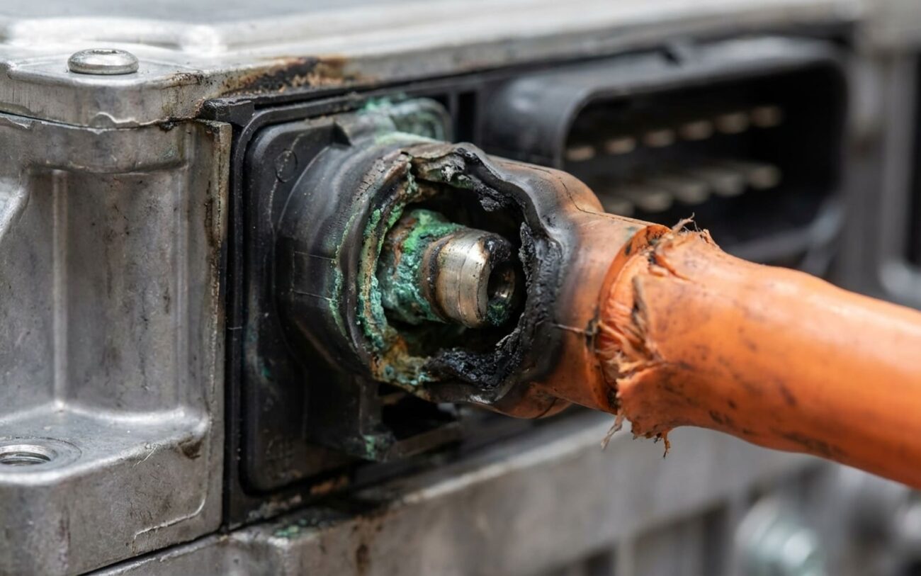
I’ve seen some dramatic failures. We’re talking sudden loss of power while driving, sometimes a loud pop that sounds like a firecracker, a burning odor, or even visible smoke from the engine bay. That smell, by the way—it’s acrid, metallic, like overheated electronics. That’s typically a failed capacitor or a shorted insulated-gate bipolar transistor (IGBT). These components handle massive current and switch at high frequencies, so when they go, they go violently.
Then there are the less catastrophic but still telling symptoms: reduced power output, a persistent limp mode, or a high-pitched whine or buzz that gets louder when you hit the throttle. That noise often comes from erratic pulse-width modulation (PWM) signals, usually caused by a failing gate driver or unstable switching in the inverter’s power stage. And if you spot pink or blue coolant pooling under the center of the vehicle—especially on models like a Toyota Prius or a Ford Fusion Hybrid—and your scanner shows inverter overtemperature codes, you’ve likely got failed internal coolant passages in the inverter itself. Coolant and high-voltage electronics are a terrible mix; that combination leads to short circuits and isolation faults every time.
Every symptom has to be cross-referenced with your scan data. I can’t tell you how many times panic-stricken owners have come in convinced they need a new inverter, only for us to find something far simpler was the culprit—like a weak 12-volt battery or a faulty sensor. That’s why we don’t just throw parts at it.
My Diagnostic Process: Separating Fact from Fiction
This is where the real technician work begins. Just because the scan tool points to the inverter doesn’t mean the inverter is bad. A lot of external issues can mimic or trigger inverter fault codes. For instance, a failing high-voltage battery can cause a P0A78 (boost converter performance) code because it can’t supply stable voltage to the inverter. A bad resolver in the electric motor might generate a P0A09 (motor control) code, even if the inverter itself is working perfectly. And I’ll tell you, one of the most common misdiagnoses out there? A weak 12-volt battery. In hybrids, that 12V system powers the control modules that enable the entire high-voltage system. If it can’t hold voltage under load, the inverter never even wakes up, leading to a no-start and a cascade of EV system warnings. Trust me on this one: check the 12V first.
Before you even think about condemning the inverter, rule out the basics. Test that 12V battery with a proper load tester, verify the HV system enablement, and check for any open high-voltage fuses or failed contactors. Once those are cleared, then you can really focus on the inverter itself. Below is a quick reference for common symptoms, what they usually mean, and the definitive tests I use to confirm the source.
| Symptom | Likely Inverter Module Issue | Common External Mimics | Definitive Test I Use |
|---|---|---|---|
| No-start with HV system warnings. | Internal pre-charge circuit failure, logic board fault, or shorted IGBTs. | Weak 12V battery, open HV fuse, failed battery contactor, or BECM fault. |
Monitor inverter DC input voltage during pre-charge with a factory scan tool. If it doesn’t hit target voltage, suspect an internal short. Back it up with a megohmmeter test on the inverter’s DC terminals for ground isolation loss. |
| Burning smell and loud noise. | Failed DC-link capacitor or shorted power semiconductor (IGBT). | Internal battery pack short, HV cable arcing. |
First, disable HV safely. Then, a visual inspection. Soot or melted metal inside the inverter housing is usually conclusive. For intermittent issues, thermal imaging during operation can pinpoint hot spots. |
| Whining/buzzing noise with power loss. | Faulty gate driver or failing IGBT causing unstable switching. | Motor resolver fault or mechanical bearing issue. |
Grab an oscilloscope with high-voltage differential probes. Look at the three-phase AC waveforms. Distorted or missing phases? Inverter failure. If the waveforms look clean but the resolver signals are erratic, you’re looking at a motor-side fault. |
| Coolant leak in inverter circuit. | Failed internal cold plate seal or cracked inverter housing. | External hose leak, fitting failure, or faulty electric coolant pump. |
Isolate the inverter cooling loop and perform a static pressure test. Clamp off the external hoses. If the pressure drops, you’ve got an internal leak. A borescope can sometimes confirm coolant inside the housing. |
| Isolation fault warning. | Coolant ingress on busbars, degraded dielectric gel, or carbon tracking on PCBs. | Damaged motor windings or compromised HV cable insulation. |
Disconnect subsystems one by one and test isolation with a megohmmeter. If the resistance is below OEM spec (usually 1–10 Megohms), you’ve found your faulty component. |
Why Inverters Fail: The Nitty-Gritty
Once you’ve confirmed the fault is actually inside the inverter module, it’s time to dig into why it failed. This isn’t about guesswork; it’s about understanding the physics of high-voltage power electronics. Most internal failures fall into a few clear categories.
Semiconductor failure is usually at the top of my list. Those IGBTs are switching hundreds of volts at high frequency, and they’re incredibly sensitive to thermal cycling and voltage spikes. Over time, that constant heating and cooling fatigues the solder joints, which increases thermal resistance and creates hot spots. Eventually, the IGBT just gives up—sometimes shorted, sometimes open. Gate oxide breakdown, either from age or an overvoltage event, is another common failure path I see.
Capacitor failure is just as critical. The DC-link capacitor is there to stabilize the high-voltage bus. When its electrolyte dries out or the dielectric material degrades—usually from sustained overheating—it can short out. That’s when you get that dramatic “pop” and often, it takes out other nearby components with it.
Coolant ingress is a catastrophic, but often preventable, cause. The inverter relies on an internal cold plate to manage all that heat. If the seals or O-rings fail—due to age, improper torque during a previous repair, or even using the wrong coolant—that coolant can leak right onto the high-voltage busbars or circuit boards. That creates a direct path to ground, triggers isolation faults, and usually destroys multiple components. It’s a mess.
Now, manufacturing defects do happen, though less frequently these days. I’ve seen certain model years across brands like Toyota and Ford with known issues, things like insufficient solder on current sensors or porosity in cast aluminum housings. These can lead to intermittent or complete failure. While I can’t list every service bulletin here, it’s always worth checking for any related to your specific vehicle, especially if you see a lot of similar failures reported in owner forums.
It’s also absolutely critical to understand what is not an inverter failure, even if it throws an inverter-related code. A failed inverter coolant pump? That’s a pump issue. A bad motor resolver? That’s a motor problem. These can trigger inverter DTCs, sure, but replacing the inverter won’t fix them. Always, always trace the signal path back to the actual source.
The Fix: What Can Be Done (and Who Should Do It)
This Is Professional Territory Only
Let me be absolutely clear: any work involving the inverter or the high-voltage system is for trained professionals only. The risks of severe electric shock, arc flash, and permanent system damage are just too high for DIY attempts. This isn’t a job for even the most skilled backyard mechanic unless they have the proper training, specialized tools, and safety gear. Don’t even think about it.
External, Accessible Issues
Internal, Modular Failures Specialist Only
Catastrophic Internal Damage
As for temporary fixes? I’ll be straight with you: I don’t recommend them. Some shops might suggest using a high-temperature coolant sealant for a minor external seep, but that’s a huge gamble. Those sealants can clog the inverter’s fine internal cooling channels, which leads to overheating and a total, much more expensive failure down the road. It’s a last-resort move at best, and it will absolutely void any remaining warranty. I’ve seen too many “quick fixes” turn into six-figure write-offs because they didn’t do it right the first time.
Proving the Repair: Post-Repair Validation
You can’t just slap in a new inverter, clear the codes, and hand back the keys. That’s asking for trouble. Validation is absolutely mandatory. For a coolant leak repair, the pass/fail standard is clear: no pressure drop after a 30-minute static test at operating pressure, and no weeping after three full thermal cycles (heat up, cool down, repeat). Make sure you use a coolant pressure tester rated for hybrid systems; a standard 15 psi tester won’t cut it for these higher-pressure systems.
For electrical repairs or full replacements, the process is more involved. After clearing codes, you need to perform a full OEM drive cycle. This allows all the systems to relearn and adapt. Then, use a factory-level scan tool to verify key parameters: DC link voltage stability, balanced phase currents, and normal inverter temperature readings under load. Any deviation from spec needs to be investigated immediately.
The final and most critical step is an isolation test using a megohmmeter. You need to test each high-voltage component individually with the system completely isolated. The inverter should read well above the OEM minimum, often 10 Megohms or more. A reading below 1 Megohm tells you there’s contamination, moisture, or insulation breakdown, and that unit must not be returned to service. It’s a safety hazard.
These tools—a proper scan tool, a hybrid-rated pressure tester, and a megohmmeter—are not optional. Skipping any one of these steps risks premature failure, or worse, serious safety hazards for the driver and anyone working on the vehicle later.
Dollars and Sense: When to Walk Away
Let’s be realistic: inverter repair is a major financial decision. Because of the high-voltage complexity and the cost of parts, there’s no meaningful DIY option for internal work. All these repairs fall under professional shop labor, and that adds up.
| Repair Type | DIY Cost | Shop Cost (Typical) | Success Rate (My Experience) | Secondary Risk if Failed |
|---|---|---|---|---|
| Complete unit replacement (new OEM) | Not applicable (HV work is professional-only) | $2,500 – $8,000 | 98% | Improper installation can cause HV arcing, damage to MG1/MG2 motors, or battery control faults. |
| Unit replacement (certified remanufactured) | Not applicable | $1,800 – $5,000 | 95% | Same electrical risks; potential for shorter lifespan or limited warranty coverage compared to new OEM. |
| Sub-assembly repair (e.g., capacitor or power stack) | Not applicable | $1,000 – $2,500 | 80% | Undetected latent faults can lead to repeat failure, potentially damaging the electric motor or battery. |
The cost often forces a tough decision. As a rule of thumb I use in my shop: if the repair cost exceeds 50% of the vehicle’s current market value, and the high-voltage battery’s state of health is below 70%, it probably no longer makes economic sense to repair. In those cases, the vehicle is likely nearing the end of its viable service life, especially if other major systems are showing their age. I’ve seen owners spend thousands to fix an inverter, only to face a failing hybrid battery six months later. You really need to consider the full picture, not just the immediate problem.
Keeping It Healthy: Prevention & Monitoring
You can’t prevent every inverter failure, that’s just how electronics go sometimes, but you can definitely reduce the risk. The most important step? Use only the manufacturer-specified coolant. The wrong type—especially one not rated for high-voltage systems—can cause galvanic corrosion in the aluminum cold plate or degrade the dielectric properties over time. Follow the coolant replacement interval religiously. On many hybrids, that’s every 100,000 miles or 8 years. Skipping it is just asking for internal corrosion and cooling inefficiency.
Listen to your vehicle. Any new whining, buzzing, or changes in EV drive behavior should prompt a scan for pending or stored inverter module DTCs—even if no warning light is on yet. A P0A78 or P1C00-series code appearing intermittently could be an early warning sign that saves you thousands.
Proactive Monitoring
If you have access to an OBD2 scanner for hybrid vehicles that can read manufacturer-specific data, use it periodically. Monitor inverter temperature, DC link voltage, and isolation resistance if your tool supports it. Catching a minor fault early—like a failing gate driver or a small coolant seep—can mean the difference between a couple hundred bucks for a seal replacement and a $6,000 inverter swap. Trust me, it’s worth the time.
Finally, keep the vehicle’s software up to date. Some manufacturers have released updates that improve inverter thermal management or adjust fault thresholds. While it’s not a fix for a hardware failure, it can definitely help avoid false codes or unnecessary limp modes, which saves you diagnostic time and headaches.
